|
|
|
|
Test GMT-GTL(-FDL)
|
Pattern Test
|
Setup
The clock and BC0 was distributed from the local TIM module (also TTCci/TTCex system was used).
Patterns were generated with the funcion GmtGtlInterconnectionTest of the gmt.exe program, written to the Sorter FPGA Sim memories of the GMT and transmitted on BC0 to the GTL board where they were read from Rec chip spys using standalone gtl.exe program. The test was performed in the new VME crate.
|
Results
No bit errors have been found. Timing was adjusted in the GMT Sorter chip firmware to guarantee correct transmission. |
|
Muon Test
|
Setup
With the same setup as in the pattern test, artificial muons were written into the Input FPGA Sim memories of the GMT. Two DT and two CSC input muons have been setup at each bx such, that GMT outputs 4 muons with the phi value corresponding to the bunch crossing number and pt values in order 8,4,2,1 so that each output muon at each bx can be identified in the consecutive modules (GTL, FDL). This allowed to debug the 80 MHz transmission via the GT crate backplane. Test has been done by reading GTL REC chip as well as by transmitting through GTL to FDL and accessing data there.
|
|
Cosmics Muon Test
|
Setup
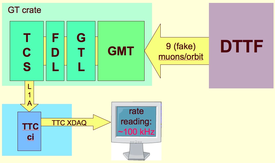
In the "Green Barrack" of the Point 5: Generated muons from DTTF were sent to GMT in 9 cycles per orbit. They passed to GTL which applied the simple cosmic test algrithms, then to FDL which generated the final OR and then to TCS which generated L1A signals sent to TTCci. At the TTCci the rate was read out. The same test has been repeated with real cosmic muons from DT chambers. Rates read at TTCci were compared with LTC rates (when only DTTF was allowed to trigger) and have been found correct (~50Hz / sector).
|
|
Diagram

|
|
|
Shortcuts:
Interface
Regional Trs.
Global Tr.
Calo. Tr.
Hardware
Schematics
Firmware
VHDL Build
VHDL Ref
Online SW
Overview
Reference
JTAG Lib
HAL
Configuration
Regs&LUTs
DAQ
RO Record
Performance
MC simulation
|

